TP5000 - LiFePO4 charge management
Charging management power supply module board for LiFePO4 batteries (3.6V)
TP5000 lithium ion battery lithium iron phosphate battery 1A current 4.2/3.6V Function: Charge lithium battery and lithium iron phosphate battery. Full of self-stop. Red and green double lights indicate.
Product introduction Advantages: Switching buck mode, the efficiency is higher than the linear charging circuit, and the heat is much smaller. The charging current is 1A and is maintained at 1A during constant current charging. No additional heat dissipation is required, which reduces the effect of heat on the charging current. Reduce charging time. An optional lithium ion lithium polymer battery or lithium iron phosphate battery can be changed with only one jumper. Parameter
- Input: 4.5-9V
- Output voltage: 4.2V/3.6V plus or minus 1% (board default lithium-ion battery 4.2V)
- Output current: default 1A
- After the efficiency test, it will be described in detail. If the buyer tests the efficiency, it is not recommended to test the battery terminal voltage. Please skip the Rs sampling 0.1 ohm resistance test. In the test, the input power is close to the circuit board, and reducing the length of the connection will have an efficiency test. Impact, it is recommended to increase the capacitance test at the input. The voltage and current test suggests that the current meter with string accuracy is not recommended to read the power supply digital display directly. The current test can be directly connected in series with the positive electrode of the battery. It is only necessary to ensure that the battery is tested below the 3.9V using a large-scale ammeter.
Features
- The whole version uses precious cermet capacitors, X7R temperature characteristics, performance + safety + stability far exceeds tantalum capacitors!
- Copper strip 5A high current small volume inductance, fully closed magnetic low loss and low interference!
- Single-sided machine mounting, overall 4 mm ultra-thin, small area, good heat dissipation, easy to install and paste heat sink on the back
- Based on DC-DC buck, the efficiency is much higher than that of a linear charging circuit, and the heat is much smaller. The charging current is 1A, but the input current is only about 0.7A.
- Optional lithium iron phosphate battery or regular lithium ion/lithium polymer battery, only one jumper can be set
- Small size, 1 hair coin size, 1A charging without additional heat
- With overheat protection, overheating will automatically reduce the current to prevent burnout
- Full-page high-precision resistor, the most stable temperature characteristic of full-size 1210 precious metal multilayer ceramic capacitor X7R
- Fully self-stop, two-color charge status indicator
- Input: 4.5-9V (recommended not to exceed 7V)
- Output voltage: 4.2V/3.6V plus or minus 1% jumper selection
- Output current: default 1A can be customized 0.5-2A, greater than 1.5A need to add heat
- 4 terminal blocks, 2 inputs, 2 batteries, and soldering position with in-line LED
Instructions:
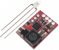
- A red, green or red-green LED is included with the circuit. You need to solder it to the circuit yourself. As shown in the baby figure, in the middle of the longest foot, the middle and long legs are close to the chip, and the shortest foot is close to the outside.
- The power supply is terminated with a 4.5-7V power supply. The current is greater than the charging current. At this time, the green light is on.
- The battery is terminated with a lithium battery or a lithium iron phosphate battery. If the battery needs to be charged, it will turn red.
- If you need to adjust the current, modify the current you need at the current sampling resistor. Sampling voltage 0.1V, current = 0.1 / resistance value
- The circuit has been soldered with a 0.1 ohm resistor and there is a vacancy
- The vacancy is soldered with a 0.2 ohm resistor and the current is set to 1.5A.
- The vacancy is soldered with a 0.1 ohm resistor and the current is set to 2A.
- Remove the original R100 (0.1 ohm), solder a 0.2 ohm resistor, set the current to 0.5A
- It is recommended to install a heat sink with a charging current greater than 1A.